Raspberry Pi project boards pt.2 – Quick2Wire
In part 1 of this series I looked at ladder board, and in the next part I plan to review the Gertboard. This post is about Quick2Wire‘s boards, where I’ve been fortunate enough to try out some alpha and beta samples.
Quick2Wire concept
There’s an interface board that connects to the general purpose input output (GPIO) headers on the Raspberry Pi, which can be used on its own as a safer way to break out the GPIO pins (versus something like a Pi Cobbler).
There are also extension boards that plug into the I2C bus (and more planned that will harness SPI). I tried out two of the I2C boards, which can be daisy chained together.
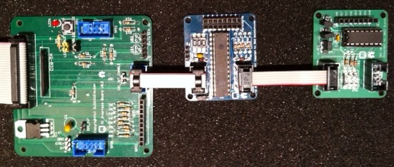
Interface board connected to I2C expander and analogue board
Interface Board
It took my son around an hour to turn this from a kit into a working board, and I didn’t have any faults to resolve. It offers a bunch of different functionality:
- 8 diode protected GPIO ports
- a push button and LED that can optionally be connected to two of the GPIO ports
- a voltage regulator for extra 3.3v
- an FTDI header for serial I/O
- I2C connection
- 2x SPI connectors
My first test for the board was to try out the push button and LED using Gordon Henderson’s Wiring Pi from the command line, and I was quickly able to read whether the switch was pushed and turn the LED on and off.
I returned to the LED later when using Quick2Wire’s Python API. Firstly I installed their GPIO admin command which lets an ordinary user do stuff with GPIO without using sudo. There are a few steps to getting this going:
- Add Quick2Wire as a Raspbian Software Source
- Install with:
sudo apt-get install quick2wire-gpio-admin
- Add your user to the gpio group
sudo adduser $USER gpio
- Log out and back in again so that the group change can take effect
- The gpio-admin command is now ready to use e.g. to allow the LED to flash:
gpio-admin export 12
The Python API is installed from github (I put it into my home directory):
git clone http://github.com/quick2wire/quick2wire-python-api
I created a little environment script (env.sh) to set up PYTHONPATH in accordance with the installation instructions:
export QUICK2WIRE_API_HOME=/home/pi/quick2wire-python-api
export PYTHONPATH=$PYTHONPATH:$QUICK2WIRE_API_HOME/src
Then when I wanted to use the Python API I could simply:
. ./env.sh
I then modified one of the Quick2Wire examples a tiny bit to give me an executable script:
#!/usr/bin/env python3

from time import sleep
from quick2wire.gpio import Pin, exported

with exported(Pin(12, Pin.Out)) as pin:
    while True:
        pin.value = 1 - pin.value
        sleep(1)
I2C Extender
The I2C extender board offers a further 16 digitial GPIO pins, and took my daughter about an hour to put together[1]. To use the board requires I2C support to be enabled on the Raspberry Pi (and as previously noted this can interfere with other GPIO stuff that uses the pins that are shared with I2C).
/etc/modprobe.d/raspi-blacklist.conf needs to look like this:
# blacklist spi-bcm2708
# blacklist i2c-bcm2708
and i2c-dev needs to be added to /etc/modules:
# /etc/modules: kernel modules to load at boot time.

snd-bcm2835
i2c-dev
If there are other modules there too (such as 8192cu for WiFi) then that’s not a problem.
Just like with GPIO it’s necessary to add the user to the appropriate security group:
sudo adduser $USER i2c
At this stage a reboot is needed (rather than just log off and back on again) so that the kernel module changes can take effect.
Once the RPi is back up and running it’s possible to see the i2c devices with i2cdetect:
i2cdetect 0
WARNING! This program can confuse your I2C bus,
cause data loss and worse!
I will probe file /dev/i2c-0.
I will probe address range 0x03-0x77.
Continue? [Y/n]
     0  1  2  3  4  5  6  7  8  9  a  b  c  d  e  f
00:          -- -- -- -- -- -- -- -- -- -- -- -- --
10: -- -- -- -- -- -- -- -- -- -- -- -- -- -- -- --
20: -- -- 22 -- -- -- -- -- -- -- -- -- -- -- -- --
30: -- -- -- -- -- -- -- -- -- -- -- -- -- -- -- --
40: -- -- -- -- -- -- -- -- 48 -- -- -- -- -- -- --
50: -- -- -- -- -- -- -- -- -- -- -- -- -- -- -- --
60: -- -- -- -- -- -- -- -- -- -- -- -- -- -- -- --
70: -- -- -- -- -- -- -- --
The example above shows that the expander board is connected at address 22 (because I fiddled with the address dip switches) and the analogue board is at 48.
I didn’t really do much with the expander board yet, but I did modify one of the Python examples to prove to myself that it would work:
#!/usr/bin/env python3

import quick2wire.i2c as i2c

address = 0x22
iodir_register = 0x00
gpio_register = 0x09

with i2c.I2CMaster() as bus:
    bus.transaction(
        i2c.writing_bytes(address, iodir_register, 0xFF))

    read_results = bus.transaction(
        i2c.writing_bytes(address, gpio_register),
        i2c.reading(address, 1))

    gpio_state = read_results[0][0]

    print("%02x" % gpio_state)
Analogue board
The analogue board is based on the PCF8591 IC, which offers 4 8bit analogue to digital inputs and a single 8bit digital to analogue output. Once again it took about an hour for my daughter to put it together[2].
I tried it out with a TMP36 temperature sensor connected to AIN0 and the following code to read out the temperature in celcius every second:
#!/usr/bin/env python3

from time import sleep
from contextlib import closing
import quick2wire.i2c as i2c
from quick2wire.parts.pcf8591 import PCF8591

with closing(i2c.I2CMaster()) as master:
    pcf = PCF8591(master)
    pin = pcf.begin_analogue_read(0)
    while(True):
        print(int(((330*pin.read())/256)-50))
        sleep(1)
Conclusion
The Quick2Wire boards bring together a modular and extensible hardware platform with a rich and easy to access software platform. I’m looking forward to getting a better understanding of the Python API so that I can do more with the boards I do have, and there’s plenty of scope for adding more boards later. It will be interesting to see what comes along to use the SPI interfaces.
Notes
1. I had some trouble initially with the expander board not showing up on i2cdetect, which came down to a very hard to spot dry joint on the board.
2. Somehow my daughter managed to get a solder splash on the component side of the board that shorted AGND and VREF. This was a total pain to diagnose and fix as I had to remove the chip holder to resolve the issue.
Filed under: code, howto, Raspberry Pi, review | 2 Comments
Tags: ADC, API, DAC, dev board, github, GPIO, I2C, PCF8591, python, Quick2Wire, Raspberry Pi, Raspi, RPi, soldering, Wiring Pi
Subscribe
Recent Comments
Chris Swan on Brewster’s Trillions Ian Osborne on Brewster’s Trillions Monki Gras 2026: Wra… on Monki Gras 2026 Chris Swan on Milo cancer diary part 20… Chris Swan on Milo cancer diary part 20…  Pinboard.in bookmarks
- Minimal SSH primer
- The Flat Curve Society
- Your Container Is Not a Sandbox: The State of MicroVM Isolation in 2026
- sideprojectslab/PD-64: A USB-PD switching PSU replacement for the C64 that also delivers galvanically insulated AC voltage
- Deepfakes are everywhere. The godfather of digital forensics is fighting back
- Tempest vs Tempest | The Making and Remaking of Atari's Iconic Video Game
- RISE RISC-V Runners: free, native RISC-V CI on GitHub
- The web is bearable with RSS
- House of Lords Digital & Communications Committee - AI, copyright & the creative industries
- CI/CD for Context in Agentic Coding: Same Pipeline, Different Rules


2 Responses to “Raspberry Pi project boards pt.2 – Quick2Wire”