Retro Computing – Planning a TMS 9995 Build on RC2014
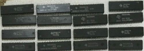
After building my RC2014 CP/M system and Gigatron I decided to dig through the pile of old integrated circuits I stashed away before leaving home thirty years ago. I don’t remember the source, but it seems that I stripped down 4 systems (which might have been something like data loggers) that had a reasonably complete set of TMS 9900 series components. So I have CPUs, serial I/O, programmable systems interfaces and more at hand (though kits with all the parts are available inexpensively from eBay).
There is already a design that I can adapt
Stuart Conner has published plans for a TMS 9995 Breadboard or PCB System, which I think will work well as the basis for an RC2014 build. The RC2014 backplane carries power, a 16 way address bus, an 8 way data bus, and the various signal lines I’ll need.
The TMS 9995 memory layout and memory access scheme isn’t identical to the Z80, so I don’t think I’ll be able to use the standard RAM and ROM modules, even though they use the same glue chips as Stuart’s design.
Stuart doesn’t just have the hardware design; he also provides some firmware, and even some debug firmware. My plan is to drop it onto a W27C512 EEPROM[1] and I’ll then be able to use a jumper on the top address line to switch between BASIC and Forth.
The other major change I’m planning is to ditch the RS232Max, as I can just use TTL levels and an FTDI adaptor.
Getting it onto RC2014
I’ve ordered a few RC2014 prototype modules, and my general plan is:
- One module for CPU, clock and serial too if I can squeeze it on.
- One module for ROM, with jumper select for BASIC/Forth
- One module for RAM (which I might just hack from my now unused RAM module since I did the CP/M upgrade)
That should leave me with a spare prototype board to lash up some sort of blinkenlights I/O board from one of the TMS9901NL I have at hand.
Given that I already have CPU, serial, EEPROM and most of the glue chips that just leaves me needing some chip sockets, a crystal and a few pullup resistors and capacitors. I’ll also get a fresh RAM, as I don’t want to mess with my working CP/M setup.
Update 20 May 2019
After a bit more noodling on the memory arrangements I’m now pretty sure that a regular RC2014 32k RAM module will work along with the pageable ROM module. It seems that Stuart (9995 breadboard design) has gone for switching the /CE signal whilst Spencer (RC2014) has gone for switching the /OE signal, but I think both approaches are equally valid. I’m using the following signal lines as equivalent:
- Z80 : 9995
- MREQ : MEMEN
- RD : DBIN
- WR : WE
I now need to figure out why Stuart uses an inverted WE/CRUCLK into the 9902 for serial? Maybe I should just ask him[2].
Update 23 Mar 2021
It seems I neglected to update this post with the origin of the TMS99xx parts stash, which I tracked down to a set of Liebherr 814A1001 Programmable Logic Controllers (PLCs) that I picked up out of the trash during my time at BMT Cortec in Wallsend. There’s a photo in the Retro Meetup Presentation I did on this project.
Next post: Retro Computing – TMS9995 on RC2014
Note
[1] I burned the K0001000 factory ROM image onto a W27C512 EEPROM to replace the supplied 27C512 one time programmable (OTP) EPROM, and it’s working perfectly in my CP/M system. As I ordered a 3 pack from eBay that leaves me with a couple to play with.
[2] I did, and the answer is that due to differences between how the TMS9900 and TMS9995 handle clocks it’s necessary to invert the clock. Apparently there are TMS9902-95 ICs out there that don’t need this, but not in the bunch I have.
Filed under: RC2014, retro, TMS9995 | Leave a Comment
Tags: 9995, RC2014, retro, TMS
Subscribe
Recent Comments
Chris Swan on Brewster’s Trillions Ian Osborne on Brewster’s Trillions Monki Gras 2026: Wra… on Monki Gras 2026 Chris Swan on Milo cancer diary part 20… Chris Swan on Milo cancer diary part 20…  Pinboard.in bookmarks
- Minimal SSH primer
- The Flat Curve Society
- Your Container Is Not a Sandbox: The State of MicroVM Isolation in 2026
- sideprojectslab/PD-64: A USB-PD switching PSU replacement for the C64 that also delivers galvanically insulated AC voltage
- Deepfakes are everywhere. The godfather of digital forensics is fighting back
- Tempest vs Tempest | The Making and Remaking of Atari's Iconic Video Game
- RISE RISC-V Runners: free, native RISC-V CI on GitHub
- The web is bearable with RSS
- House of Lords Digital & Communications Committee - AI, copyright & the creative industries
- CI/CD for Context in Agentic Coding: Same Pipeline, Different Rules


No Responses Yet to “Retro Computing – Planning a TMS 9995 Build on RC2014”