I first came across GreenQloud at GigaOm Structure Europe last year. It’s a cloud service based in Iceland that is powered entirely from renewable energy. I bumped into Eiki and Bala again last week at London CloudCamp, and gave them my sob story about hosting. They’ve very kindly offered to provide free hosting for my (mostly OpenELEC for the Raspberry Pi) downloads in exchange for a little recognition (like this).
![]()
Let me know what sort of download speeds you get? From my own testing it seems better than the BuyVM box (after the move to Las Vegas).
Filed under: cloud, Raspberry Pi | 8 Comments
Tags: bandwidth, GreenCloud, hosting, openelec, Raspberry Pi, Raspi, RPi
DevOps is really about design
I the early part of the ‘unpanel’ session at last night’s post Cloud Expo London CloudCamp there was a good deal of debate about DevOps and what it means. Some people talked about new skill mixes, others talked about tools. These are I think simply artefacts. The more fundamental change is about design. At the risk of repeating myself, if something is designed for cloud then it is designed for operations, so DevOps is an expression of industrial design maturity.
At the same event Pat Kerpan from CohesiveFT challenged conventional wisdom by saying ‘go for production first’ (rather than go for the low hanging fruit of dev and test). I think his point was that unless you choose a path that can be seen to work in production, then you might never actually get there. Perhaps the way to build a bridge between these two seemingly opposite approaches is by the use of continuous deployment, which has much in common with ‘DevOps’ .
So here’s what I think is going on:
- The first stage of (industrial) design maturity is design for purpose – a cottage industry. The people who make software (Dev) aren’t the ones keeping it alive in production (Ops) and there are likely many inefficiencies and resultant costs. This (unfortunately) is how much enterprise IT works[1].
- The second stage of design maturity is design for manufacture. This optimises the process of making software, so we might see practices like continuous integration, but doesn’t concern itself with the operational environment. This is how most packaged software is made, as the people cutting the code aren’t the ones holding the costs of looking after it in production (hence the myth of software support).
- The third (and final) stage is design for operations, which optimises for end-end cost of ownership for the software and its care and feeding in the production environment. Anybody running a software as a service (SaaS) platform must (at least aspire) to achieving this level as they will be at a competitive disadvantage if there are inefficiencies between Dev and Ops. Of course most enterprises that do in house software should also be trying to get here, which is why DevOps shouldn’t just be for lean startups.
I’ll take all the debate about skills and tools as evidence that we (as a community in general) don’t think enough about design and design maturity. This is perhaps where PaaS comes into play – people that don’t think about design very much can use something with design baked in by those who do.
Notes
[1] I caught a few references to ‘enterprise grade’ at CloudCamp last night, used in a way that implies higher quality. This is of course at odds with Don Box – So Long, 2006 ‘The blogosphere embraced the term “enterprisey” to describe the lack of quality that previously had no name’.
Filed under: architecture, cloud, software | 1 Comment
Tags: cloud, cloudcamp, design, DevOps, maintenance, manufacture, maturity, paas, purpose, saas
After bringing my Nanode based temperature sensor back to life I thought about some other projects that I might do. One was simply to add an external sensor to the Nanode project, and another was to turn my slow cooker into a sous vide water bath (along the lines of ‘Sous Vader‘). Those projects would need a temperature sensor that could withstand weather/immersion, and the waterproof DS18B20 fits the bill (such as this on eBay).

The two sensors that I ordered arrived today, and since I’ve got a Raspberry Pi on my desk I thought I’d try them out with that first. I quick hunt for DS18B20, onewire and 1wire in the forums suggested that things would be very easy (e.g. too trivial for anybody to explain) or very hard (e.g. requiring ninja kernel hacking skills). As I didn’t come across any code samples I was starting to fear the latter, but luckily it turned out to be the former. A bit more digging around led me to this tutorial by Matthew Kirk on the University of Cambridge site. Things have clearly moved on since he wrote it though, and I didn’t need to patch my (reasonably up to date) Raspbian to get w1-gpio and w1-therm support. It was simply a question of connecting the three wires black-GND red-3.3v and white-GPIO4 and I was all set (I didn’t use a pull up resistor).
With the appropriate modules installed (sudo modprobe w1-gpio && sudo modprobe w1-therm) the temperature can be read with:
cat /sys/bus/w1/devices/serial_number/w1_slave
The serial_number is something like 28-000003ea00b4 and the one on my desk is presently reading something like this:
48 01 4b 46 7f ff 08 10 ad : crc=ad YES
48 01 4b 46 7f ff 08 10 ad t=20500
So anything that can read from a file can read the temperature, and the crucial part in all of that is t=20500, which is 20.5 Celcius.
I’m off to solder some header pins onto the wires so that they don’t fall out of my breadboard so easily…
Filed under: howto, Raspberry Pi | 7 Comments
Tags: 18B20, 1wire, DS18B20, kernel, modprobe, module, onewire, Raspberry Pi, Raspi, RPi, sensor, temperature, thermometer, w1-gpio, w1-therm
OpenELEC 3.0 RC2
The second release candidate for OpenELEC 3.0 (featuring XBMC 12 ‘Frodo’) is now available (official announcement). There have been a flurry of changes over the past few weeks (over 275 by my count), but the OpenELEC team are saying that this will be one of the final release candidates before 3.0 final.
If you’d like to download an SD card image to install on a Raspberry Pi then it’s available from the official_images section of the Pi Chimney resources site. RC2 is 2.99.2, and later builds will be available from the same link.
To install the image first unzip it and then use Win32DiskImager (if on Windows) or dd (if on Linux or Mac) to write the image file to your SD card (which needs to be 1GB or larger).
If you’re already running OpenELEC on your Raspberry Pi then just get the release bundle from the OpenELEC.tv download page, extract the files (using 7zip or WinRAR or similar) and follow the Manually Updating OpenELEC guide.
Filed under: Raspberry Pi | Leave a Comment
Tags: 3.0, file, Frodo, howto, image, openelec, Raspberry Pi, Raspi, RC2, release, RPi, SD card, update, upgrade, XBMC
Lenovo S206 – first impressions
First the really good news – Lenovo (or more specifically their fulfilment partner Digital River) managed to take an order from me and ship (on time) without some major disaster happening (as I’ve suffered before, repeatedly). They seem to have entirely given up on supplying order tracking information, which is little change in practice to the past system of providing bad order tracking references. At least this time the system worked as it’s supposed to[1].

Why an S206?
My daughter wants a laptop for her upcoming birthday, and when she discovered that there were such things as pink laptops specific colour requirements emerged. I’d have been happy to forgo pink for performance if I’d have been able to get another fast/small/cheap machine like my son’s Lenovo x121e, but I was only recently moaning that such machines pretty much don’t exist. As it became obvious that I’d have to sacrfice some performance to get a small machine (11.6″ screen) at a decent price (~£250) my search narrowed to the HP DM1 and Lenovo S206, which both sport AMD E Series APUs. Since the S206 was available in Pink, and was cheaper I was leaning that way, though I was a little concerned about the performance of the E1200 processor. The deal was sealed by a special offer I stumbled across on the Lenovo web site for the E1800 version with 500GB hard drive at under £250. The PINKMADNESS voucher code that I used seems to have been a short and limited offer to clear down inventory of machines with Windows 7 (32bit).
SSD Upgrade
I was at an event a little while ago where somebody said ‘if you’re not using an SSD in your PC then you’re literally waiting your life away’, and I’ve since switched all of the regularly used household machines over. It took a sacrifice from my dismembered media playing netbook to free up an SSD, but I expect it will get more use this way.
I booted up the installed hard disk for long enough to redeem the £14.99 Windows 8 Pro upgrade offer that’s still on until 31 Jan, then it was time to swap over.
Getting inside the S206 isn’t straightforward – there’s no access hatch like on the X121e. Thankfully Lenovo are open with their hardware maintenance manuals, and with the S206 guide on screen I had good guidance. Getting at the battery, RAM and hard disk involves removing the bottom. Firstly there are a couple of screws under rubber feet, and then the plastic casing needs to be gently eased away from the body of the machine (with a plastic opening tool).
Once I got everything up and running on a fresh Windows 7 x64 install performance was disappointing. Windows Experience Index was reporting 5.6 for disk (no better than the original disk) and SiSoftware Sandra benchmarked a meagre 135MB/s. I checked that the BIOS was set to ACHI (it was), and then upgraded the AMD chipset drivers (having originally used the ones that came on the supplied hard disk). New drivers fixed it, and WEI went up to 7.6 with Sandra clocking 265MB/s.
In use
The chicklet keyboard and screen are pretty much the same as the X121e, which means that this is a nice machine for the money.
There’s just a trackpad, as it’s only ThinkPads that get trackpoints. After using the trackpad on my Chromebook for the past few weeks it was a struggle switching to different gestures, but once I adjusted it’s a decent enough way of getting around.
Subjective speed was initially hampered by the poor I/O performance noted above, but now that’s fixed it feels quick in use. The CPU is the weakest part of the performance story (with a WEI of 3.9), but with the SSD on board and an OK graphics subsytem it will be quick in everyday use (and it’s unlikely to be used for CPU bashing video transcoding).
Conclusion
I expect my daughter will be delighted with this machine, and won’t care very much about a weak CPU. With the SSD on board it should perform well for the applications she’s likely to run on it (browsing, homework, and maybe some casual gaming).
Notes
[1] After writing this post I found an email from Digital River in my spam folder entitled ‘Lenovo UK – Order no. xxxxxxxxxxx – No shipment date’. It continued:
RyanDear Mr/Mrs Swan,
We are contacting you in relation to your recently placed order on the Lenovo Online Store. Unfortunately, the build of the following product you ordered is delayed in manufacturing product name (IdeaPad S206). Although we do not have an estimated ship date, we hope to be able to confirm a ship date in the coming days.
As soon as we have an estimated ship date, you will be notified via email.
We regret any inconvenience this may cause.
The email was dated the day that it arrived, so the machine must have been sent before the email. Clearly Digital River still can’t find their bum with both hands, and I’ll count it as a happy coincidence that the laptop actually shipped within the advertised time. Who knows, I may even be sent another, or get a refund when they tell me that the build is further delayed.
I’m also wondering who ‘Ryan’ is and how that name found its way into the greeting. I guess it’s all part of the Digital River bluehornet.com ‘individualized email experience’.
Update 1 (28 Jan 2013) I just got an email from Digital River saying that my order had shipped – the same order that I received 4 days ago. True to past form the tracking link in the email and on the order status site doesn’t work.
Filed under: review, technology | Leave a Comment
Tags: 11.6", ACHI, AMD, APU, benchmark, driver, E1200, E1800, lenovo, performance, review, S206, ssd, x121e
Scream if you want to go faster
BuyVM, the main hosting service that I use for OpenELEC builds at resources.pichimney.com (and openelec.thestateofme.com), moved servers from San Jose to Las Vegas over the weekend. Whilst the move was happening I temporarily redirected traffic to my secondary VPS to avoid any down time.
I’ve just switched things back to the main server[1], as it has a much larger bandwidth allowance, but I suspect/fear that it’s going to be much slower than before (moving files between the boxes, which is part of the build process, has been about 10x slower). Let me know in comments below if you experience issues downloading image files or release bundles?
One option for speeding things up might be to distribute files using BitTorrent, and I’d be happy to use my servers as seed boxes. Let me know if you’d be interested in trying this (in the comments below)?
Notes
[1] I thought I’d hit publish on this a couple of days ago, but apparently not
Filed under: Raspberry Pi | 2 Comments
Tags: bandwidth, bittorrent, BuyVM, download, hosting, image, openelec, release, SD card, torrent
It got a bit cold
I wrote last week about re-establishing my Nanode based temperature monitoring in anticipation of some cold weather. It came, though it’s not as cold as it was last year (when I was seeing -7.5 being recorded):
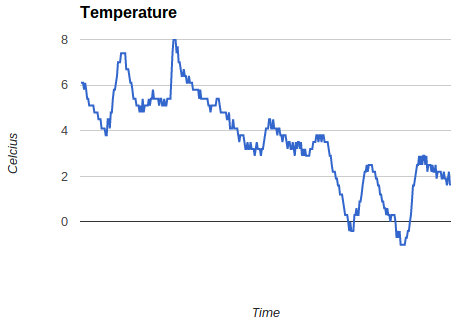
It’s clearly warmer in the garage than it is outside, where there is snow lying on the ground. That’s likely to be down to heat from the fridge, freezer and microserver out there. It’s fairly easy to see the day to night ups and downs (even without me putting on an accurate time axis or labels). I was also intrigued to see how much warmer the garage got for a little while when I put my car back in there after a trip out last week (that’s the peak up to 8C). I’m now thinking about adding another sensor outside so that I can compare the temperatures.
Filed under: Arduino | Leave a Comment
Tags: chart, Nanode, temperature
TL;DR
I haven’t got this working (yet). There may even be limitations to the hardware that mean this couldn’t work.
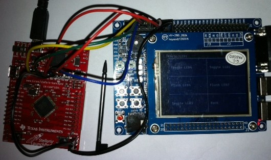
The general idea was to use a cheap ($4.99) Texas Instruments Stellaris Launchpad (LM4F120XL) board in place of a pricier ($34.95) Dangerous Prototypes Bus Blaster. All of the basic pieces seemed to be there – USB connectivity, JTAG breakout.
I’ve got as far as having OpenOCD playing along with the ICDI, but I’ve not yet been able to make it work as a JTAG programmer.
Why?
Last weekend I was following Zizzle’s excellent guide on using cheap Chinese STM32 based boards with touch screens, which I wrote about myself in ‘STM32 Dev the easy way‘. Some of the examples used Bus Blaster, and showed that it was faster, easier and more flexible than programming via the USB/serial port. I don’t have a Bus Blaster, but I do have a couple of Stellaris Launchpad boards.
How
The Stellaris Launchpad has a set of holes onboard that will take header pins to break out JTAG. TI provide a guide on their wiki, (superficially) explaining how these can be used. Sadly it’s not entirely clear whether JTAG support is generic, or limited to other TI devices. I hooked up the boards like this:
 OpenOCD
Zizzle’s examples with the Bus Blaster used Open On-Chip Debugger (OpenOCD) as the software plumbing. Support for TI’s In Circuit Debugging Interface (ICDI) wasn’t present in the version bundled in the VM I was using, but is available in more recent dev builds. I cloned the project from git and set about putting in place the dependencies that I needed to make a new version with ICDI support enabled. This blog post from Scompo traces out similar steps to the ones I took if you’re interested in the detail.
Once OpenOCD was correctly built, and I had the right udev settings to allow use of the USB device without sudo I was able to connect to the Launchpad. The next stage was to modify Zizzle’s config files to use the TI board rather than Bus Blaster:
OpenOCD config
Zizzle starts OpenOCD with the command line ‘openocd -f jtag/stm_board.cfg’, and the stm_board.cfg looks like this:
telnet_port 4444
gdb_port 3333

gdb_memory_map enable
gdb_flash_program enable

source [find jtag/busblaster.cfg]
source [find target/stm32f1x.cfg]
The busblaster.cfg looks like this:
interface ft2232
ft2232_device_desc "Dual RS232-HS"
ft2232_layout jtagkey
ft2232_vid_pid 0x0403 0x6010
and I found a corresponding file for the Launchpad that looks like this:
interface hla
hla_layout ti-icdi
hla_vid_pid 0x1cbe 0x00fd

# unused but set to disable warnings
adapter_khz 1000
So with a change to the second to last line to reference the ti-icdi.cfg rather than the busblaster.cfg I was all set. Sadly this is what I see when I try to start things up:
Open On-Chip Debugger 0.7.0-dev-00135-g76afade (2013-01-13-08:03)
Licensed under GNU GPL v2
For bug reports, read
        http://openocd.sourceforge.net/doc/doxygen/bugs.html
adapter speed: 1000 kHz
adapter speed: 1000 kHz
adapter_nsrst_delay: 100
Runtime Error: target/stm32f1x.cfg:27: invalid command name
"jtag_ntrst_delay" in procedure 'script'
at file "embedded:startup.tcl", line 58
at file "jtag/stm_board.cfg", line 8
at file "target/stm32f1x.cfg", line 27
and that’s where I’m presently stuck :(
Conclusion
It would be very nice if the Stellaris Launchpad could be used as a generic JTAG programmer, and all of the pieces seem to be available, they’re just not quite moving together for me yet. It’s quite possible that TI have locked things down so that it isn’t actually possible, which would perhaps be a bit mean of them, but might explain why I’m not just following the steps of somebody more knowledgeable’s howto. I’ll write updates if anything changes.
Filed under: making | 5 Comments
Tags: Bus Blaster, dev board, ICDI, JTAG, launchpad, LM4F120XL, OpenOCD, programmer, Stellaris, STM32, ti
Chromebook – a week on the road
I spent the past week as exec in residence for the London Fintech Innovation Lab, working with the 7 winning startups based in the shiny new Level 39 Technology Accelerator at Canary Wharf. It seemed like the perfect chance to try out my Chromebook in a more work oriented setting.
Battery life
I was brave, and decided not to take the power supply with me. I wouldn’t be using my Chromebook all the time, so I thought 6.5 hours would be enough to get me through each day. It was. I wasn’t even running for the power supply when I got home as there was always enough juice left for any sofa surfing that I wanted to do.
Google Docs Only
I encountered one hiccup where an old Word document I imported didn’t format correctly, and rather than spending ages reformatting it I waited until I was home to sort it out on my PC. At a push I could have used remote desktop, but it wasn’t that urgent.
I’ve pretty much switched over to Google Docs from MS Office anyway, so the Chromebook worked fine with all of my ongoing stuff.
OpenVPN
The launch of the iOS client for OpenVPN spurred me on to get it working with the Chromebook. It’s fine if I run it from the command line in a dev mode crosh shell e.g.:
sudo openvpn my_vps.ovpn
I have still utterly failed to get things working with the regular (non dev) approach using .onc files and importing private keys etc., but I’m not feeling too bad about that, as there’s a post in one of the support groups from a member of the OpenVPN team saying ‘the interface for OpenVPN in Chrome OS seems to be pretty much unusable for your average user‘. Basically Google need to provide a tool to parse .ovpn into .onc, and some better howto guides would be nice too.
Telephony
I’ve been using Google Voice for some time, and presently have things set up so that my mobile phone and Skype In get routed there (which would be easy if I was in the US, but takes a bit of SIP Sorcery from the UK). In the past I’ve not made much use of the gmail chat functionality for voice calls, but I gave it a try this week and it works well. I was almost tempted to buy some credit so that I can call none US numbers, and then I realised that I could use my US Skype ToGo number, which gives me free calling to the UK via a Skype subscription and Skype pay as you go rates for any other number I might call. Of course it would be great if there was a Skype app for ChromeOS, or if Google Voice was rolled out to the UK, but I won’t be holding my breath on either of those things.
ChrUbuntu
I haven’t needed it. ChromeOS has been sufficient.
Conclusion
Google Apps got me through the week pretty much fine from a software point of view, and the Chromebook stood up well from a hardware perspective. It was great to be liberated from a power cord AND have a decent keyboard. I didn’t feel like I was compromising using a cheap machine (and I’m pretty sure most of the people stopping by for a chat probably mistook it for an 11″ Macbook Air).
Filed under: review, technology | 1 Comment
Tags: battery, Chromebook, Chrubuntu, OpenVPN, telephony, Voice, voip
STM32 dev the easy way
A while ago I bought an STM32 dev board from China on eBay, as it seemed to have so much more than the official Discovery boards coming with:
- A 2.4″ LCD with touch screen input
- 4 Pushbuttons (and a Reset button)
- 4 LEDs
- 2 Variable resistors
- A Micro SD slot
- A buzzer
- RS232
- 2 USB sockets
- JTAG
- A whole bunch of GPIO pins
In sum a whole bunch of awesome stuff. Sadly sometimes when things look too good to be true they are. After waiting ages for it to arrive I discovered that most of the documentation was in Chinese. It ran a pretty little demo app, but I didn’t know where to start with programming it. I put it on the shelf in the hope that one day something would show up to help, though realistically I expect it to gather dust – maybe I’d have a go at using the LCD for another project.
Zizzle to the rescue
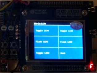
At the end of October I saw a piece on the Dangerous Prototypes blog ‘Tutorial: STM32 boards and TFT LCD touchscreens‘, which linked back to Zizzle’s ‘STM32 LCD touch screen demo‘. I downloaded the VirtualBox image containing the tools and sample code, but didn’t do anything with it as I didn’t feel like I had the time. I shouldn’t have worried; when I finally got around to trying it yesterday I was up and running in minutes – watching the YouTube guides and clicking along in my own virtual machine. Another few minutes and I had customised menus on the touch screen:
It was also pretty straightforward to get debug messages from printf into a console.
I then went on to waste hours trying to get a TI Stellaris LaunchPad to work as a JTAG programmer in place of the BusBlaster that Zizzle had used, but that’s another story.
Why this works
Setting up tool chains for embedded devlopment is fiddly, but virtual machines make a great container for all of that effort. I’m now starting to wish that I’d had a go using a Linux VM for Andrei’s ‘STM32F3 Discovery + Eclipse + OpenOCD‘, but I thought it would be much harder to get USB devices working in the VM than it turned out to be (NB Andrei has since done a Windows version of his instructions).
Conclusion
Putting a complete tool chain in a VM image makes it super easy to get going with a dev board, especially when accompanied with good quality videos explaining how things work. Thanks Zizzle :)
Filed under: making | Leave a Comment
Tags: ebay, LCD, STM32, touch screen, VirtualBox, VM

