OpenELEC 3.0 Released
![]() OpenELEC 3.0.0 has been released, which means that this popular distribution for XBMC is now in a stable version on Raspberry Pi. Raspberry Pi downloads for an SD card image file (.img.zip) and a copy of the release bundle (.tar.bz2) are on the Pi Chimney resources site.
OpenELEC 3.0.0 has been released, which means that this popular distribution for XBMC is now in a stable version on Raspberry Pi. Raspberry Pi downloads for an SD card image file (.img.zip) and a copy of the release bundle (.tar.bz2) are on the Pi Chimney resources site.
I’ve done some tidying up on the site, so all the old official images and dev builds are now tucked out of the way.
As previously posted I’m going to stop doing images for regular dev builds now. Anybody that wants to just use OpenELEC should be using the stable release, and anybody that wants to tinker should have the wherewithal to do their own image file (or can use the upgrade process from a stable image).
I’d like to thank the dev team over at OpenELEC.tv for all their hard work in pulling this together.
Filed under: Raspberry Pi | 25 Comments
Tags: 3.0, 3.0.0, download, image, openelec, Raspberry Pi, Raspi, release, RPi, stable, XBMC
Review – Lenovo X230
Shortly after starting my new job it became apparent that I’d need a new laptop. As most of the other CohesiveFT team use Macs (and iWork) I was very tempted by the 11″ Macbook Air, but its limited memory and need for dongles to connect to things like VGA and network dissuaded me. I may come to regret this (due to iWork related issues), but I instead went for a Lenovo X230 – it’s roughly the same travel weight as the MBA, can take 16GB RAM, and has proper ports on it.

Buying
For reasons I can’t fathom the X230 is loads cheaper in the US than the UK. I very nearly bought one last year in the Black Friday sale as it was pretty much half the price of an equivalent UK model. When I went looking again there was no sale, so I took to eBay and found a bargain i5-3320M based model that came with an Ultrabase.
Upgrades
Before I even started using it I upgraded to an SSD (a Samsung 840) and 16GB RAM, which ensures spectacular performance – the worst part is the built in HD4000 GPU (though even that isn’t too bad):
I then installed Windows 8 Pro so that I could use Hyper-V for Linux VMs.
Awesome keyboard
Having used an X220 for much of last year I was a bit skeptical about the new chiclet keyboard on the X230 (which I expected to be like the one on my son’s X121e). I shouldn’t have worried – the X230 keyboard is the best I’ve ever used on a laptop. It might even be quite simply the best keyboard I’ve ever used (and I’m usually quite fussy about my keyboards – mostly using nice old HP ones).
Not a tablet
I’ve hardly been using the tablet features of my previous Lenovo X201 Tablet, which is why I went for the straight X230 rather than the tablet version. I know that Windows 8 is designed for touch, but the X230 Tablet isn’t a touch screen anyway, and I’m using Start8 to make Windows 8 behave like a proper desktop operating system.
Battery life
My machine came with the 6 cell 44+, which seems good for 5 hours of real world use – not enough for a day on the road without a charger, but still pretty respectable. For serious endurance there’s a 9 cell battery (the 44++) and an Ultrabase style battery slice (the 19+).
Ultrabase
I like being able to connect to my large monitor, home network and KVM switch with minimum fuss, so it was cool that the machine came with an Ultrabase. I doubt I’ll ever much use the DVD writer it came with, but it’s there if need be. The new Ultrabase seems more plasticy than earlier models, but it gets the job done.

Unlike earlier Ultrabases I get the impression that this one is just for desktop docking, and isn’t really intended to be carried around – it’s not heavy, but there’s just too much bulk.
Screen
The screen is lovely and bright, and with a matt finish that keeps reflection down.
Minor annoyances
I kept touching the trackpad with my hand when using the trackpoint, so I installed the Synaptics drivers and disabled it (it’s also possible to turn it off in the BIOS).
I also found that the standard Windows drivers wouldn’t let me output audio through the Ultrabase, which was fixed with the Lenovo drivers.
Conclusion
The X230 is the best laptop I’ve ever used. It’s light, has good endurance, and spectacular performance. If I could run an OS-X VM in Hyper-V to get iWork then it would be perfect.
Filed under: review, technology | 9 Comments
Tags: lenovo, review, ssd, X230
Ruining the firework display
This is a cross post from the CohesiveFT corp blog.
For many years setting off fireworks was a labor intensive task, with people running around lighting blue touch papers. That’s been changed in recent years, and large displays are now automated. Somebody programs a script into a box, then presses the Go! button to set things off. Once in a while there is some horrible error in setting the timings (like mixing up seconds and milliseconds) and all of the fireworks go off pretty much at once (with some newsworthy examples in recent years from Oban and San Diego).
As you can see, the results can be pretty impressive, but it lacks the duration and drama of the planned event – particularly when it was expected to be set to music.
Filed under: cloud | Leave a Comment
Tags: automation, fireworks
Filed under: presentation, technology | Leave a Comment
Tags: architecture, consumerisation, consumerization, container, framework, html5, mobile, native, strategy, web
SDN – flow control and APIs
This is a cross post from the CohesiveFT corp blog.
A friend and former colleague recently asked me, “on the SDN front – anything you’d recommend reading in terms of positioning, and compare/contrast of quantum vs. openflow vs. onePK vs…….?”. This was my reply:
OK… based on my limited understanding (I don’t consider myself anything close to being an expert on this stuff yet – I have that mountain to climb in front of me).
OpenFlow is a protocol for describing L2 paths. It’s more of a policy definition than a language, and I met a professor at Princeton a while back who was looking into the issues involved in parsing OpenFlow (it isn’t pretty).
Quantum is the OpenStack API for L2/L3. There are various plugins available to a bunch of OpenFlow implementations (which will immediately give you an impression of how ‘standard’ OpenFlow itself is), plus plugins for other (virtual) networking gear.
onePK is a combination of APIs and management tools for Cisco gear. If it talks IOS then onePK can be stuck in front of it.
It looks like the world is splitting into 2×2 directions:
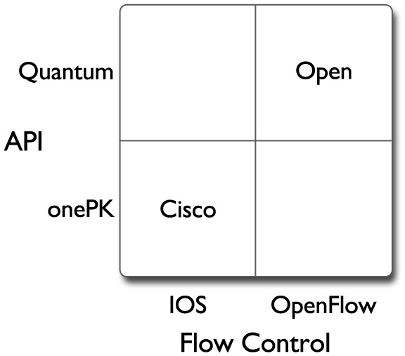
In one dimension it’s about flow control, and the players are OpenFlow and flow control protocol buried in IOS. The network equipment vendors that aren’t Cisco seem to be rushing to adopt OpenFlow, as it gives them leverage against IOS. Cisco itself would seem to have no interest in OpenFlow (why would it?) but I’m sure there will be others that come up with ways to parse OpenFlow into IOS incantations.
The other dimension is about APIs, and the players are Quantum and onePK, so again we see a Cisco versus rest of the world split, but also again there’s an incentive (for everybody except Cisco) to bring Cisco gear into the rest of the world fold. The twist here is that APIs aren’t exclusive (though Oracle are still trying to persuade a judge that they are), so onePK might well end up being the Trojan horse that Cisco has rolled up to its own gates (once somebody cranks out a Quantum to onePK adaptor).
As inevitably happens with these things the bottom left and top right corners are the interesting ones. Bottom left is anchored on Cisco with IOS and onePK. It’s a little more interesting than a past world of just IOS, but it’s about preserving the Cisco networking hegemony. Top right is OpenFlow and Quantum, and is where the real disruptive action is going on.
Filed under: CohesiveFT, technology | Leave a Comment
Tags: API, iOS, network, onePK, OpenFlow, OpenStack, protocol, Quantum, SDN
My New Job
I’ve started a new job as CTO for CohesiveFT. It’s a great company with a great team and some great products and services. As I’ve known many of the people since before the company was founded this post could be subtitled ‘a brief history of CohesiveFT’.
The people and pre-history

Alexis Richardson was the instigator. He’d seen that the financial services industry was building lots of software that did basically the same stuff (and added no differentiation or value to the firms involved), and though that open source was the answer – along the lines of JP’s open source first approach[1]. The idea was to bring together a syndicate of banks to create a mutualised open source platform (predominantly for the back office). This went by various names as he sought interest and investment (OpenClub is one I remember best). There was even some hope that firms might contribute existing platforms – I think the whole concept of technical debt was less well understood then, but the project had legs even if it was just for new stuff[2].
Alexis wore the title of ‘Founder’ when CohesiveFT came together. Later he teamed up with Matthias Radestock at LShift to create RabbitMQ, and implementation of the AMQP message oriented middleware protocol. RabbitMQ was spun out of the CohesiveFT/LShift partnership to be acquired by VMWare (in a for them classic engineering led infanticide deal), which took Alexis away from CohesiveFT to be an executive at VMWare. I’m sure he’s doing something pivotal for the Pivotal Initiative these days.
 I first met Craig Heimark in a pub near Liverpool Street. Alexis was camping in the offices of Evolution, where Craig was one of the advisors, and it had been suggested that Craig might be interested in the OpenClub project. With a background in trading, risk management and senior IT leadership Craig was the perfect person to see the potential of the project, and well placed to help find investors. Craig certainly was interested, and went on to become founding CEO of CohesiveFT.
 Shortly after the meeting with Craig and Alexis I saw a blog post from Patrick Kerpan announcing his departure from Borland (where I’d got to know him after they’d bought his source code management company Bedouin). I knew that Pat had worked in financial services before Bedouin, and thought he’d be a perfect addition to the OpenClub project. What I didn’t know at the time was that Craig and Pat had worked together back at O’Connor & Associates (and subsequently Swissbank following the [reverse] takeover), so at the same time I was introducing Alexis and Pat to each other Craig was doing the same.
Pat was interested enough in the project to come out to London and meet with people to discuss its potential, and I recall a lunch meeting in Canary Wharf where all four of us got together. Pat asked me what I thought was going to be hot in the industry and my answer was ‘software appliances’ (as that’s what I’d been calling them), though I noted that VMWare were holding their first ‘virtual appliance’ competition, so it seemed likely that would be the term that would take hold. Pat had made a comment to me years earlier that “installation is a software hate crime”, and it seemed that there was much to like in the idea of packaging stuff up into a deployable virtual machine. A few weeks later Pat called me (with some excitement in his voice) to say that he was going to make a virtual machine factory. Pat joined CohesiveFT as founding CTO, and their first product had been conceived.
Server3
Server3 (Server Cubed) was originally christened Elastic Server on Demand (ESoD), a name that lives on for its SaaS implementation elasticserver.com. As a virtual appliance factory it takes a ‘bill of materials’ (which might also be thought of as a recipe) for a virtual appliance, and then assembles that appliance to a given output specification. The end result is that functionally identical appliances can be put together for a range of different operating environments such as the virtualisation platforms used in many private clouds or the deployment packages used for public clouds (which Server3 can deploy to directly).
Since having a factory industrialises the process of putting together software for deployment it can borrow from other aspects of industrial design, so it’s possible for the appliances made by Server3 to have a common ‘chassis’ to provide consistent interfaces for monitoring and management.
I’ve used Server3 in the past for some of my own projects, often taking advantage of its ability to integrate directly with Amazon Web Services such as EC2 and S3. More recently Server3 has recently added support for IBM SmartCloud where it’s able to add diversity to the image library that comes as part of the standard service. Most exciting for me right now is that OpenStack support is imminent – it’s already showing on the site as ‘(coming soon)’, and I know the dev team are focussed on finishing that job. As more and more companies use OpenStack internally, and more and more providers choose OpenStack for their public services it’s going to be an important platform, and Server3 will provide an easy way for people to get the stuff they need running on it.
VNS3
Virtual Network Server cubed started its life as VPN-Cubed, but I think the change in name reflects that there’s much more to it than just a virtual private network. VNS3 is used to create overlay networks, and the overlays can be within a cloud, between clouds, between a private data center and a cloud (or clouds) or simply between multiple data centers.
Network overlays are useful for a number of reasons:
- Security by keeping network traffic inside of encrypted tunnels.
- Protocol Support for stuff that the native (service provider) network doesn’t do (e.g. multicast). I’ve used VNS3 myself to connect together a grid that depended on multicast where the network of the underlying service provider (Amazon) didn’t support it.
- Consistency of addressing schemes etc. It’s possible to run different collections of machines inside of VNS3 using the same IP allocation scheme, which can greatly simply migration between environments (e.g. dev->test->production), or troubleshooting (where an exact copy of a given environment can be cloned for fault finding).
The VNS3 overlay can connect into a typical network edge device to provide connectivity into regular corporate networks.

As the VNS3 managers have an API it makes it part of the movement towards software defined networking (SDN), which I plan to write more about in a subsequent post.
Context3
Context-Cubed is a system for the deployment and management of application topologies. If an application sits inside a single (virtual) server then things are pretty simple, but once an application spans multiple machines then it usually involves some degree of dependency management – the web server should wait for the app server should wait for the database. This type of dependency management also happens within a single system, and is dealt with using something like init; so Context3 is essentially init for distributed systems.
It isn’t just for managing startup dependencies, as it can also help with runtime scaling (up or down) so that within a multi tiered application there is enough resource to satisfy demand, but not too much (which might be running up a usage bill).
Wrapping up
I’ve only just started with CohesiveFT, but I’ve known the people and the products for long enough for it to feel something like a homecoming for me. The company has some great products and services to help people harness the power of cloud computing, and I’m looking forward to helping people understand that capability and get started with using it.
Notes
[1] Arguably financial services is a vertical market problem rather than a generic problem, and so should be served by the commercial community, but that clearly wasn’t working out.
[2] I think what’s subsequently happened at OpenGamma shows that open source can succeed in the financial services arena, but perhaps that ‘OpenClub’ was too broad in its ambition.
Filed under: cloud, CohesiveFT, technology | Leave a Comment
Tags: aws, deployment, factory, IBM. cloud, image, industrial design, management, multicast, network, open source, OpenStack, SDN, security, topology, virtual appliance, virtual machine, vpn
What’s going on in laptop land?
Prices are up – way up. I’d love to get some better metrics, but for now I’ll just go on a few specific data points from observations over the last couple of months.
When I was deciding whether or not to get a Chromebook after Christmas I could have picked up a white AMD (E-1200) based Lenovo S206 for £199.99 from Amazon, the best they can do now is the older E300 model for £299.99 – £100 (50%) more.
When I bought my daughter’s Pink (E2-1800) S206 it was £249.99[1] it’s now £100 (40%) more .
When I was shopping around for my daughter’s laptop I wanted a 11.6″ screen, which was hard to find, but there were a load of machines at the £239.99-£249.99 price point with 15.6″ screens. Those machines now seem to be £329.99-£369.99 if you can get them at all.
If feels like supply is thin, and prices have risen accordingly – a bit like the HDD shortage following the flooding in Thailand a little while ago. But this time I can’t think of an event that’s caused the shortage.
Meanwhile the Samsung ARM Chromebook has come down (on Amazon) from £229 to £224.
I know that the £ has been weakening, but nowhere near enough to explain these price movements. Something else is going on, and I’d love to know what?
One thing does come to mind – the end of promotional pricing for Windows 8. The Wintel hegemony was in bad enough shape due to the awful UX of Windows 8. Things will only work out worse if Wintel is priced uncompetitively against the Chromebook and Tablet competition.
Note
[1] That was a sale price for the E2-1800, but I could have easily picked up an E-1200 for the same money.
Filed under: technology | Leave a Comment
Tags: AMD, Chromebook, Intel, laptop, pricing, rises, Windows
I’m starting a new job at the end of the week, and I’ve been agonising over whether I should treat myself to a shiny new laptop. I’m *really*tempted by an 11″ MacBook Air[1], but at the same time I’m inclined to hold off until a Haswell-ULT/ULX version comes along (which might then have an all day battery rather than 5hrs).
In a brief moment (of insanity?) I wondered if a Surface Pro would fit the bill. And then I remembered this tweet:
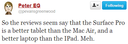
That got me thinking… What if Apple made something that brought together the best of both worlds from the MBA and iPad? I imagine these qualities:
- Similar form factor to existing MacBook Air
- 10hrs+ battery life
- 3G/4G connectivity (as well as WiFi)
- Maybe a touch screen (though I could live without that)
- Cheap
When I got to the final point my bubble burst. Apple just aren’t going to do that. There’s a strict heirarchy that cannot be disrupted: iPod Touch, iPad Mini, iPad, MBA, MacBook Pro. There might just be room for some kind of iPad/MBA hybrid, but it would come in at $800, which seems pretty premium to me.
Then it struck me… The ChromeBook costs less that the iPod Touch, and has most of the features I’m looking for. What it can’t do is run a bunch of VMs locally. In fact it can’t even run a bunch of the most popular apps (Skype, WebEx and Netflix seem to be the biggest bugbears).
That missing stuff – it matters now. It makes the Chromebook look like a toy. I’m guessing however that we’re seeing a classic case of innovators dilemma here – today’s toy is tomorrows sharper tool – disruption.
PS I don’t think this is necessarily a huge problem for Apple. They’ve got a long sheet for selling premium stuff, and an (ARM based?) MaciPad would likely sell well to a certain audience. The ones who are going to be left without a seat when the music stops are the traditional WinTel vendors (and their problem right now is that I’m not being offered something I’d rather buy than an MBA as it seems that every Ultrabook with a screen <13″ is some ridiculous experiment in touch based user experience design – well done Windows 8 and Metro).
Notes
[1] I’m also considering the Lenovo X230, which is about the same travel weight, but a good deal larger (and a lot cheaper). If there’s a choice to make then it hinges on industrial design, price, and whether I need to edit Keynote presentations.
Filed under: technology | 3 Comments
Tags: apple, Chromebook, disruption, innovators dilemma, iPad, MacBook Air, MBA, Metro, Surface Pro, ultrabook, Windows 8
Presenting with a Chromebook
I decided to use my Samsung ARM Chromebook for a presentation at Brighton Pi last night. It did not go well.
Creating the presentation
Using Google Docs instead of Powerpoint was pretty straightforward. I never do much fancy with my slides – usually just a visual anchor or a few bullet points, so no real challenge. I was able to find functions easily, and in general the interface felt simpler and cleaner. I wouldn’t be surprised if I was quicker making the presentation in Google Docs. I did most of the work on my main Windows machine, but when I needed to do a few tweaks it was easy to modify things on the Chromebook. So far so good.
Preparation
Working Offline
I didn’t know whether I’d have network access at the venue, so it was crucial that I got Drive working offline. It was not obvious how to do this, and searching around found me lots of conflicting instructions. I don’t really understand why offline capable isn’t the default. I also don’t understand why the Available Offline column doesn’t seem to do anything in the Chromebook file manager thing.
HDMI
I’m not sure how ubiquitous HDMI capability is yet for projectors etc. A lot of venues I’ve spoken at have been geared up for VGA and that’s it. I had some confidence that I’d be OK this time as the Raspberry Pi also has HDMI output, but I checked in good time so I could revert to another laptop with VGA if need be.
Unstable – they weren’t kidding
I switched my Chromebook to the Dev – Unstable channel in order to get the Chrome RDP app working. This has turned into a bit of a disaster on few fronts:
- My Chromebook now randomly locks up and needs to be power cycled to get going again.
- Google Voice dialling from within Gmail has stopped working. No matter what number I dial I get a message like this:

- I may have a working RDP client, but it doesn’t seem to play nicely with the SSH tunnels I use to secure access to my network, rendering it pretty much useless.

On the night
No mirror
The Chromebook will only mirror to an external display (e.g. the projector I was using) if it supports the same resolution as the LCD screen. 1366×768 might be a popular resolution for 11″ and 12″ laptops, but I’m guessing it’s not so widely supported for beamers, plasmas etc.
Unlike Powerpoint it seems that Google Docs doesn’t have a feature where it will present the slides on multiple screens (like the one in front of you and the one behind you).
Replug HDMI – hang
The irony – it hurts – my Chromebook just crashed as I was about to write about my Chromebook crashing.
I did a number of demos with the Raspberry Pi that required me to unplug the HDMI cable from the Chromebook and plug it back in later. Every time I did that the Chromebook hung.
It hung a bunch of times without provocation too.
This very much disrupted the flow of my presentation.
At least sharing is easy
When I got home I made the presentation public. It was loads easier than uploading stuff to SlideShare (though in the interest of curation I should probably put something there too).
Conclusion
I’m glad I was presenting in front of a small and friendly audience, and that there were plenty of questions to carry me through the numerous restarts. At least the Chromebook doesn’t take minutes to reboot. The instability is maybe my own fault for being impatient and going onto a dev build, but the dual display stuff needs sorting out. I expect it will be a while before I try this again.
Filed under: could_do_better, grumble, Raspberry Pi, technology | 1 Comment
Tags: beamer, Chromebook, crash, dual, freeze, google, Google Docs, hang, HDMI, lock up, offline, presenting, projector, screen, share, unstable
Do VMs dream of real networks?
With apologies to Philip K. Dick.
This post is going to address three topics:
- The relationship between a virtual machine (VM) and its network connection(s).
- The changing perimeter
- The role of APIs in controlling network configuration
The common theme is dreams, or perhaps de/re(ams) – as the last two topics touch on whether something is de- or re-. I’ll explain…
Dreams of connectivity
Patrick Kerpan and I stepped out of Cloud Expo last week for a cuppa and a chat, and the conversation inevitably came around to the relationship between cloud architectures and networks. His company (CohesiveFT) makes a virtual network overlay that used to be called VPNcubed that was renamed to Virtual Network Server cubed (VNS3). I used it myself a few years back when I was experimenting with deployment of a PaaS fabric to a hybrid (public/private) infrastructure environment. I made the following point:
The VM doesn’t really know the difference between an eth0 and a tun0 – it’s just dreaming a different dream of network connectivity.

Could that be a dream bubble or a cloud?
CC Some Rights Reserved by Akakumo
This isn’t entirely true… If the connection to a VPN overlay (tun0) is made from within the VM itself then it needs a (pretend) physical adaptor (eth0) to bind to. But the rules of the game don’t have to work that way. The management layer could present the VM with a tunnelled end point and the VM would have no idea.
The underlying point here is that network layers 1,2 & 3 have become entirely made of software (and hence fungible) in virtualised environments, and the virtual machine doesn’t (and shouldn’t) have any idea when things are being moved around. Not only do VMs dream of connectivity, but we can have Inception into those dreams. That’s a fun magic trick when things are being configured manually, but it becomes really powerful when the network is configured by software through APIs.
De or Re pt.1 – perimeters
For some time the Jericho Forum has been taking about deperimeterisation – the idea that the network perimeter as presently defined in most organisations will disappear. I never thought it was realistic that the perimeter would go away entirely[1], so for many years I’ve talked about reperimiterisation – where the perimeter contracts around core assets/data. In the enterprise the first step comes in moving the perimeter from the entire network (including desktop etc.) to around the data center. In the case of mobile we can already see mobile application management creating perimeters around specific apps and the data they handle.
In many ways the traditional perimeter was about management convenience – good guys inside, bad guys outside – build a wall between them. Of course that simplification was never true, and often helped the malicious insider, and got in the way of doing business with the legitimate outsider. In an age of manual configuration it was just a good first approximation that made the problem space manageable.
Software defined networks let us have much more precision in tailoring perimeters to the threat and the business case.
De or Re pt.2 – software, networks and APIs
Software Defined Networking (SDN) is the new hotness at the moment, especially since VMWare spent $1.2Bn on Nicera to get the networking piece for their Software Defined Data Center (SDDC) story. There seem to be some who are taking software definition to mean that the network is itself a software entity. Whilst this can be true it’s certainly not the most efficient way of moving packets around – that takes optimised hardware. Chris Hoff has recently been tweeting that we should call them Software Refined Networks, and I’m inclined to agree. Specialised hardware isn’t going away, we’re just going to get smarter about how we (re)configure it.
APIs are now stepping into the yawning hole between manual changes to network config (which usually involve a trouble ticket and somebody with a Cisco certification) and changes to network config that have always been automated (and somewhat invisible) – like Routing Information Protocol (RIP). There will certainly be places where networking is pure software (the first part of this post illustrates that), but as the tributaries merge into great rivers the software piece will be about getting the most out of hardware.
Conclusion
Networks have had virtualisation (in the from of virtual local area networks – VLANs) since before virtualisation hit the mainstream in other areas like (distributed[2]) compute and storage. The issue here is that the configuration of that virtualisation was primitive, and it hasn’t meshed well into other areas of data center automation. That’s changing now, and as VMs dream of connectivity we can use software through APIs to refine networks and reperimeterise security boundaries. Networking (and network security) just got interesting again.
Notes
[1] In the words of my friend Colin Constable we still need the perimeter (and its firewalls etc.) to ‘keep the lumps out’. As Bruce Schneier has pointed out – the old threats don’t go away.
[2] Virtual machines of course aren’t new, but VMs on mainframes weren’t particularly interesting or challenging from a network perspective.
Filed under: cloud, software | Leave a Comment
Tags: cloud, define, defined, deperimiterisation, deperimiterization, networking, perimeter, refine, refined, reperimiterisation, reperimiterization, SDN, software, virtualisation, virtualise, virtualization, virtualize, VLAN, VM, VMs

